Si tratta di un dipolo NON risonante su nessuna delle bande amatoriali (tranne, forse, i 15 metri). Il dipolo e' caricato capacitivamente alle estremita' con due elementi trasversali. Il carico capacitivo allunga elettricamente il dipolo senza introdurre perdite.
E' importante sottolineare che per essere efficiente (nel senso della resistenza di radiazione e delle perdite) un'antenna NON deve necessariamente essere risonante.
L'articolo che segue l'avevo scritto nel 2012 nel mio blog precedente (chiuso dal provider), subito dopo l'installazione dell'antenna.
I mounted the antenna in December 2012. The reasons to buy such an antenna are as follows... I was looking for an aerial with the following characteristics:
- horizontally polarized (no vertical, ’cause of the noise)
- to be used in the higher bands (20-17-15-12-10) meters
- light weight, good robustness, small footprint for DOA restrictions
- having a small, but yet usable directivity
- limited cost, easy to install by myself alone
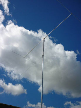
It seemed to me that the “Dualbeam” dipole by ProAntennas was the solution. (For more detailed specs, here is the link to the product page DUALBEAM Pro). The photo on the left is a snapshot of my DBPro installed on top of the building (30 meters above surrounding land, and 6 meters above the terrace floor).
At that time I found impressive the manufacturer declaration that the antenna was usable (with the help of an external ATU) also on 40 and 80 meters. Wow! Was it really so?
After having the antenna mounted, I found that the performance was poor in the 40 metres band. It was also similar to my windom on 20 meters, and got a sensible improvement on 17-15-10 meters. The measurements I got from the real antenna was quite surprising to me with respect to those declared by the manufacturer. Following are
the measurements at the transmitter end, with SWR measured on a DAIWA SWR meter.
Measurement conditions :
- Coaxial cable length, from antenna feed point to radio : 27 meters
- Coax type : Belden H155, 50 ohm
- Antenna height : – above terrace : 6 meters – above ground : 30 mts.
- Used tx power to measure SWR : 20 W, CW
- SWR meter : DAIWA CN-720B

That is quite non-sense…..unless you want to see a lower SWR due to cable loss !!

Radiation diagram for 14.250 MHz (20 meters band).
SWR =~5:1
Z = 42-j95

Radiation diagram for 18.100 MHz
SWR =
Z =

15 meter band

10 meters band
Conclusions : It’s clear that the efficiency of the antenna system relies (as usual) on the cable , expecially to
transform the impedance to values that the ATU (Antenna Tuner) /Transmitter is able to manage.
What’s the cable magic length? Simply it doesn’t exist, as if we optimize for one band, it will not be good for another one.
Since the cable introduces an amount of loss not completely neglectable…… the solutions could be :
- to optimize the antenna for a specific band and accept the compromise on the other bands
- to use a very low loss transmission line, and insert a current balun;
- to adopt an ATU at the base of the antenna
- better throw away the voltage balun and ….. use a balanced open transmission line….
The last bullet imposes anyway to take into account the efficiency of the balanced-to-unbalanced by a current balun on the transmatch (or use a balanced ATU)
73 de IZ0IRH, Mario
Appendix:
By simulation, I found that a little better SWR value on 20 meters can be obtained simply by modifying the profile of the capacitive loads, in the way shown below:

Scrivi commento